circuit-using-latex
Lesson-2: Basic Components
Draw a straight wire from (0,0) to (4,0):
Method-1:
\begin{circuitikz}
  \draw (0,0) -- (4,0);
\end{circuitikz}
🔍 Explanation:
-
– → draws a plain wire
-
(0,0) → starting point
-
(4,0) → ending point
Method-2: (Recommended)
\begin{circuitikz}
  \draw (0,0) to[short] (4,0);
\end{circuitikz}
Output:

Junctions and Nodes
Simple Node (Connection Point):
Syntax:
\draw (2,0) node[circ] {};
Wire with a Node:
Syntax:
\draw (0,0) to[short] (2,0) node[circ] {} to[short] (4,0);
Example:
\documentclass{article}
\usepackage{circuitikz}

\begin{document}

\begin{center}
\begin{circuitikz}

    % Example 1: A simple wire with a junction (node) in the middle
    \draw (0,0) to[short] (2,0) node[circ] {} to[short] (4,0);

    % Example 2: A vertical wire branching down from the node
    \draw (2,0) to[short] (2,-2);

\end{circuitikz}
\end{center}

\end{document}
Output:

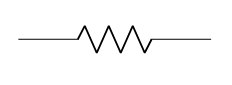
Draws a resistor horizontally from x=0 to x=3:
Syntax:
\begin{circuitikz}
    \draw (0,0) to[R, l=$R_1$] (3,0);
\end{circuitikz}
Explanation:
- R: Specifies the component is a Resistor.
- l=
$R_1$: Adds a label above the component. The$signs are used for mathematical formatting (italics, subscripts).
Example:
\documentclass{article} % The type of document

% The Preamble
\usepackage{circuitikz} % We are importing the circuit tool

\begin{document}

    % The Drawing Area
    \begin{center}
        \begin{circuitikz}
            % This draws a wire from (0,0) to (2,0) with a Resistor in the middle
            \draw (0,0) to[R] (3,0);
        \end{circuitikz}
    \end{center}

\end{document}
Output:
If you want to name the resistor:
\draw (0,0) to[R, l=$R_1$] (3,0);
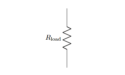
The Vertical Resistor:
\begin{circuitikz}
  \draw (0,0) to[R, l=$R_{\rm load}$] (0,3);
\end{circuitikz}
Explanation:
- R_ → creates a subscript for R
{\rm load}→ typesets the subscript text in upright (roman) font instead of italic
Output:
🔹 Capacitor
Horizontal Capacitor:
\begin{circuitikz}
  \draw (0,0) to[C, l=$C_1$] (3,0);
\end{circuitikz}
Output:

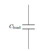
Vertical Capacitor
\begin{circuitikz}
  \draw (0,0) to[C, l=$C_{\rm load}$] (0,3);
\end{circuitikz}
Output:
Horizontal Inductor
\begin{circuitikz}
  \draw (0,0) to[L, l=$L_1$] (3,0);
\end{circuitikz}
Output:

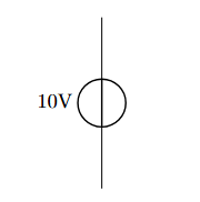
🔹 Voltage Sources
DC Voltage Source
\begin{circuitikz}
  \draw (0,0) to[V, l=10V] (0,3);
\end{circuitikz}
Output:
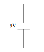
Battery
\begin{circuitikz}
  \draw (0,0) to[battery, l=9V] (0,3);
\end{circuitikz}
Output: