circuit-using-latex
Lesson 3: Voltage Sources, Grounds, and Nodes
1. Voltage Sources
To power our circuits, we use voltage sources.
| Component | Code | Description |
|---|---|---|
| DC Source | to[V, l=5V] |
Generic circle with +/- |
| Battery | to[battery, l=9V] |
Standard battery symbol |
| Battery (Alt) | to[battery1] |
Alternative style |
Example:
\draw (0,0) to[V, l=9V] (0,3);
2. Grounding
Ground is a specific node shape in Circuitikz. It is typically attached to the end of a wire or a specific coordinate.
Syntax:
\draw (x,y) node[ground]{};
3. Connection Nodes
To show that wires are electrically connected (and not just crossing), we use filled circles (nodes).
Method A: The Suffix (Recommended):
You can add specific line-ending styles to component options.
to[short, -*]: Line ends with a dot.to[short, *-]: Line starts with a dot.to[short, *-*]: Dots at both ends.to[short, -o]: Ends with an open circle (terminal).
Method B: The Explicit Node
Place a node manually at a coordinate.
\draw (2,2) node[circ]{};  % Solid black dot
\draw (2,2) node[ocirc]{}; % Open white circle
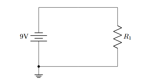
Example:
\documentclass{article}
\usepackage{circuitikz}

\begin{document}

\begin{center}
\begin{circuitikz}

    % Voltage source
    \draw (0,0) to[battery, l=9V] (0,3);

    % Top wire
    \draw (0,3) to[short] (4,3);

    % Resistor
    \draw (4,3) to[R, l=$R_1$] (4,0);

    % Node at (0,0)
    \draw (0,0) node[circ]{};

    % ground
    \draw (4,0) to[short] (0,0) node[ground]{};

\end{circuitikz}
\end{center}

\end{document}
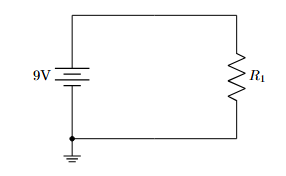
Output:
To Flip the Battery:
\draw (0,0) to[battery, invert, l=9V] (0,3);
Output: